Contents
Managing Multiple LEDs
Lets get started with some programming.
With the components listed on the overview page, we will learn about:
- the basic Arduino Program structure.
- connecting components (LEDs and buttons) to the Arduino.
- using data to drive how the program operates (data driven programming).
- use a switch/button to change how the LEDs blink.
- various programming constructs including "for" loops and "if" statements.
Program Template
In the Arduino IDE, if you click the "file" menu, then "new", the IDE will open a new window with a program that contains two functions similar to the following:
void setup() {
  // put your setup code here, to run once:
}

void loop() {
  // put your main code here, to run repeatedly:
}
This is the smallest possible Arduino program. It consists of two functions named setup and loop.
As it stands, the two functions contain nothing other than a comment providing some very basic guidance. We will now put some code into them.
Basic Blink Program
As the comments in the setup and loop functions state, the:
- setup function contains code that is run once - when the Arduino is turned on or reset. We use this function to initialise or set things up for later use.
- loop function contains code that is executed (or run) repeatedly. This is the main part of the program and it defines the things that your project does.
We will modify the template code, so that it looks like the following:
void setup() {
  // put your setup code here, to run once:
  pinMode(LED_BUILTIN, OUTPUT);
}

void loop() {
  // put your main code here, to run repeatedly:
  digitalWrite(LED_BUILTIN, HIGH);
  delay(1000);
  digitalWrite(LED_BUILTIN, LOW);
  delay(1000);
}
Tip, before uploading the code, make sure you have correctly selected the Arduino Board you are using (e.g. Uno, Mega etc) and correctly selected the port that the board is connected to. If you are unsure how to do either of these things, checkout the basics section of setting up the IDE.
Once you have modified the code and verified the board and port, you can upload it to your Arduino. There are 3 ways you can upload code from the Arduino IDE as follows:
- Click on the "Sketch" menu, then "upload".
- Press Ctrl-U (Control-U) on your keyboard. Mac users use ⌘-U (Command-U or Apple-U).
- Click the upload button on the toolbar.

Once you have uploaded the code to the Arduino, the LED marked L on the Arduino will slowly blink - continuously.
If you have any errors during the upload process, first check that
your code exactly matches the code shown above. Also, double check
that you have correctly selected the correct Arduino and port
(refer to basics in setting up the IDE.)
This should address most of the problems. If it does not, try googling
the error messages that you will find in the black messages panel
at the bottom of the IDE.
Tip: If you have to resort to googling error messages
try googling the first error message (not the last ones and not all of
them at once) until you clear all of the problems.
Tip: Double check that you have entered the program
correctly. If necessary, copy and paste the code shown above.
Referring back to the code, we learnt that there are two functions named setup and loop.
In our program, the setup function consists of the following line of code:
pinMode(LED_BUILTIN, OUTPUT);This line of code sets up the Built-in LED (marked L on the Arduino) as an OUTPUT.
The loop function consists of the following code:
  digitalWrite(LED_BUILTIN, HIGH);
  delay(1000);
  digitalWrite(LED_BUILTIN, LOW);
  delay(1000);
These lines of code are executed (one at a time in the order specified) to turn the Built-in LED ON and OFF. Between each operation is a delay(1000); As its name implies, delay function will cause a delay for the time specified. The amount of time to delay is specified as 1000 which is measured in milliseconds. One millisecond equals 1/1000th of a second. Another way of saying it is there are 1,000 milliseconds in a second.
But how do we know that the parameter is measured in milliseconds?
The answer to that question is because the
documentation
that the good folks at Arduino have provided for us tells us precisely
that. Most of the Arduino functions are documented on the Arduino web
site. Other functions, such as the C standard library and 3rd party
contributors are documented elsewhere.
For now, we will stick with functions that are
documented
on the Arduino web site. This includes documentation for basic C/C++
statements that we will use such as "for" and "if" statements.
I recommend referring to the Arduino documentation web site as we cover
new ground in this tutorial.
External LED
Next we will add an external LED connected to the Arduino. For this step, you will need:
- One LED - the colour does not matter.
- One 470 Ω current limiting resistor - refer to the resistor identification page in the reference for information about resistor values.
- One breadboard
- Hookup wire - preferably one black wire and one other wire of any colour (but not red or black).
Using the hookup wire and breadboard, connect the LED to the Arduino
as per the following diagram:
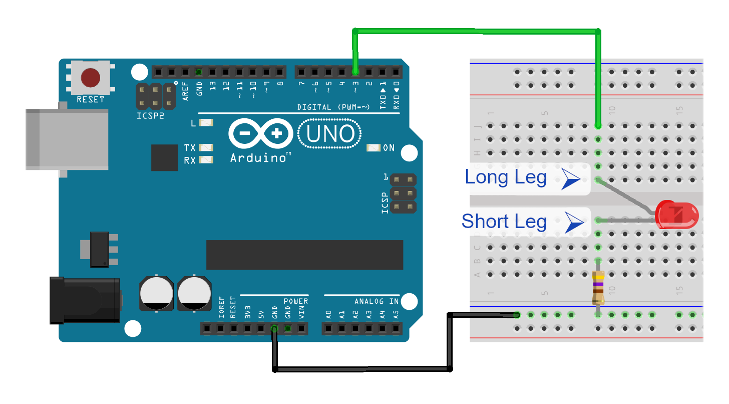
The connections are as follows:
- Use a black wire to connect GND on the Arduino to the long "bus" marked with a blue (or black) line on the breadboard.
- Insert your LED to the breadboard so that it bridges the gap in the middle and the short leg on the LED is on the side that the black wire is connected to.
- Insert your 470 Ω resistor so that it connects the short leg of the LED to the long "bus" that the black wire is connected to.
- Use a wire of any colour (but not black or red) to connect the long leg of the LED to pin 3 on the Arduino.
One of the benefits of colour coding is to ensure that there aren't any short circuits. A short circuit can potentially cause the destruction of your Arduino. By following at least the Red (VCC) and Black (GND) colour scheme, it is very easy to see if you have accidentaly connected the two directly together - and thus correct the mistake before finding out about your mistake the "hard way" and potentially blowing up your Arduino in the process.
You will note that in the more complex projects, I will tend to colour code wires according to their function, but may use other schemes that make sense for that project or part of the project. This makes it easier to correctly hook things up and if something does go wrong, trace potential causes of any problems.
Modify the code so that it reads as follows:
const int LED0 = 3;

void setup() {
  // put your setup code here, to run once:
  pinMode(LED0, OUTPUT);
}

void loop() {
  // put your main code here, to run repeatedly:
  digitalWrite(LED0, HIGH);
  delay(1000);
  digitalWrite(LED0, LOW);
  delay(1000);
}
Once you have made the changes, upload the program. If you have done everything correctly the LED on the breadboard should be blinking. If it is not, check the following:
-
The LED is inserted with the correct orientation.
The short leg of the LED, or Cathode, connects to the resistor which in turn is connected to ground. - The long leg on the LED, or Anode, is connected to PIN 3 on the Arduino.
- The Built-in LED is no longer blinking - if the Built-in LED is still blinking, then the program shown above has not been correctly uploaded to the Arduino.
Note that in the code, I have introduced a constant named LED0.
Use of constants, such as LED0, makes your life easier. As I show in the
video, if you need to change the pin the LED is connected to it is
a simple matter of just changing the value assiged to LED0.
Another benefit of using named constants such as LED0, HIGH, LOW and
so on is that you do not need to remember lots of detailed information.
This means that you can concentrate on the big picture (i.e. your
project) as opposed to having to fill your mind with nitty gritty
details such as LED0 being 3 (or 2?) or having to know what the
values that LED_BUILTIN or HIGH or LOW are.
More External LEDs
In this step, add as many LEDs as you want to to the circuit. Simply repeat the process outlined in the previous step. In the video, I take it one LED at a time and introduce structures such as the array and NUM_LEDS calculation and explain them. You can skip directly to this step if you wish, but if you are new to Arduino, I would recommend following the intermediate steps in the video.
When you connect the LEDs to the Arduino, you can use any of the pins numbered 2 through 13 inclusive (do not use pins 0 or 1).
However, if you want to follow along
with the video, you should follow the ones that I have used.
These are: 3, 5, 6, 9, 11, 12 and 13.
Modify the code, so that it reads as follows:
/*
 * Following is the list of pins that you have connected the LEDs to.
 * If you follow my connections, then the LED array will be set
 * correctly. If you have used different pins for the LEDs then
 * you will need to list the pins that you have used in place
 * of my pin numbers.
 */
int LED [] = {
  3, 5, 6, 9, 11, 12, 13
};
const int NUM_LEDS = sizeof(LED) / sizeof(LED[0]);

void setup() {
  for (int idx = 0; idx < NUM_LEDS; idx++) {
    pinMode(LED[idx], OUTPUT);
  }
}


void loop() {

  for (int idx = 0; idx < NUM_LEDS; idx++) {
    digitalWrite(LED[idx], HIGH);
  }
  delay(1000);
  for (int idx = 0; idx < NUM_LEDS; idx++) {
    digitalWrite(LED[idx], LOW);
  }
  delay(1000);
}
You will note that I have made a slight deviation from the video by removing the const definitions of LED0, LED1 etc and just listing the pin numbers in the LED array. I do suggest this as an alternative in the video ( and explain why) when connecting the last two LEDs (12 & 13).